Becoming an LED packaging enterprise with high core value
頁(yè)橫幅/img-banner4.jpg)
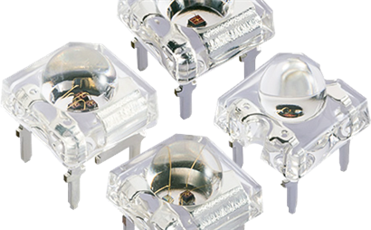
People habitually refer to infrared emission tubes and infrared reception tubes as infrared pairs. The appearance of an infrared pair tube is similar to that of an ordinary circular light-emitting diode. For those who first come into contact with infrared detectors, it is difficult to distinguish between the transmitting and receiving tubes.
1) Use a multimeter to measure the Rxlk resistance deflection of a 500 or other model pointer type multimeter, and measure the interpole resistance of an infrared pair tube to distinguish the infrared pair tube.
Criterion 1: Under the condition that the end of the infrared probe is not illuminated by light, exchanging the probes for measurement results in a low forward resistance and a high reverse resistance of the transmitting tube. When the black probe is connected to the positive electrode (long pin), the emitting tube has a low resistance (1k-20k). The receiving tube has high forward and reverse resistances.
Criterion 2: When the black lead is connected to the negative pole (short pin), the emitter tube has a high resistance, while when the resistance is low and the pointer of the multimeter changes with the intensity of light, the pointer that swings is the receiver tube. (1) Measure the forward resistance when connecting the black lead to the positive electrode and the red lead to the negative electrode.
A high resistance means that the pointer of the multimeter does not move at all.
2) Discriminating the method of electrification experiment
Connect a light-emitting diode and a resistor in series with the measured pair of tubes, as shown in Figure 2. The resistance in the figure plays a current limiting role, with a resistance value ranging from 220 ohms to 510 ohms. LED light emitting diode is used to display the working status of the tested infrared tube. Use a remote control (TV remote control, etc.) to press the arbitrary button of the remote control towards the tested tube. When the LED is on, the tested tube is an infrared receiver tube. If it is not bright, it is an infrared emission tube.
Measuring the working voltage and current of infrared light-emitting diodes on the transmitter circuit can easily determine how well they work. When measuring the working voltage at both ends of the pipe, it is usually zero in static state (i.e. when no button is pressed), while in dynamic state (i.e. when a certain button is pressed) it will jump to a smaller voltage value. Due to the coding method of the remote control system, the construction of the driving circuit, and the difference in the working power supply voltage, the voltage value is usually between 0.07 and 0.4V, and the probe should also tremble slightly. When using a digital multimeter for measurement, its measurement value will generally be higher than the value measured by a pointer multimeter, usually between 0.1 and 0.8V.
If the watch needle trembles when static but does not tremble when dynamic, both tremble when static and dynamic, neither tremble when static and dynamic, and there is no significant difference between the dynamic voltage and static voltage, it can be concluded that the infrared light-emitting diode is working abnormally. If the driving amplifier circuit is normal, it is mostly due to damage to the infrared light-emitting diode.
Infrared light-emitting diodes should be kept clean and in good condition, especially the spherical emission area at the front end, which should not contain pollutants such as dirt or be damaged by friction. Otherwise, the infrared light emitted from the tube core will reflect and scatter, directly affecting the propagation of the infrared light. The light may reduce the flexibility of the remote control, reduce the control interval, and the heavy may cause malfunction, leading to remote control failure.
During the working process, all parameters of infrared light-emitting diodes must not exceed the limit values. Therefore, when replacing and selecting, attention should be paid to the model and parameters of the original pipes, and they cannot be changed arbitrarily. In addition, the current limiting resistor of infrared light-emitting diodes should not be arbitrarily changed. Due to the wide wavelength range of infrared light, infrared light-emitting diodes must be paired with infrared receiving diodes for use, otherwise it will affect the flexibility of remote control and even cause loss of control. Therefore, when selecting a replacement, it is important to pay attention to the wavelength parameters of the emitted infrared light signal.
The hardness of infrared light-emitting diode packaging materials is lower, and its high-temperature resistance is worse. To prevent damage, the solder joint should be far away from the root of the pin during the day, the welding temperature should not be too high, and the welding time should not be too long. It is best to use metal tweezers to clamp the root of the pin to assist in heat dissipation. The shaping of the pin bending switch should be completed before welding, and neither the tube nor the pin should be subjected to force during the welding process.
Address: 5th Floor, Building 12, Changfeng Industrial Park, Dongkeng, Fenghuang Street, Guangming District, Shenzhen, Guangdong Province
Tel: 13632942401
Email: [email protected]

Copyright ? 2023 Tianshi All Rights Reserved 粵ICP備2021179733號(hào)


產(chǎn)品圖/3mm凸頭.jpg)